

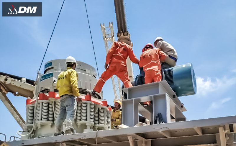
As high-efficiency fine crushing equipment, hydraulic cone crushers are widely used in metal mines, construction aggregates and other fields. The quality of their installation and commissioning directly affects equipment operation stability, production efficiency and service life. The following are key precautions during installation and commissioning, covering the entire process from foundation preparation, equipment installation, hydraulic system debugging to no-load and load testing.
I. Pre-installation Preparation
1. Foundation Design and Construction Requirements
- Foundation bearing capacity must meet 1.5-2 times the total weight of the equipment (including material impact force), and concrete strength grade should not be lower than C30
- Foundation plane flatness error should be controlled within ±5mm, and levelness error ≤0.1mm/m
- Reserved bolt hole position deviation ≤10mm, depth deviation ±20mm, hole wall verticality deviation ≤5mm
- Drainage system should be installed around the foundation to avoid water accumulation affecting equipment and concrete foundation life
2. Equipment Arrival Inspection
- Verify consistency of equipment model, specifications with the contract, and check if accompanying technical documents (instruction manual, qualification certificate, assembly drawing) are complete
- Inspect key components such as main machine, motor and hydraulic station for transportation damage and ensure seals are intact
- Count the quantity of wearing parts, spare parts and special tools, with focus on crushing chamber liners, hydraulic components and other precision parts
- Check if the type of lubricating oil and hydraulic oil meets the requirements in the instruction manual, and unopened oil products should be within the shelf life
Note: If any damaged or missing equipment parts are found, take photos immediately and contact the supplier. Never assemble damaged parts without authorization.
II. Key Points for Main Machine Installation
1. Main Machine Positioning and Leveling
- When using lifting equipment, lifting points must be at the designated positions on the equipment. Never arbitrarily select lifting points (special lifting lugs are usually provided on the top of the frame)
- After positioning the main machine, level it in both X and Y axes on the frame's upper plane using a level meter, adjust with wedge iron, ensuring levelness error ≤0.1mm/m
- Tighten anchor bolts in diagonal sequence gradually and evenly, with final torque meeting the requirements in the instruction manual (usually 300-500N·m)
- Confirm the equipment levelness is qualified before secondary grouting. Use non-shrinkage concrete for grouting, with thickness not less than 50mm
2. Transmission System Installation
- Motor installation position must ensure parallelism with the main machine pulley, with axial deviation ≤0.5mm and radial deviation ≤1mm
- Adjusting V-belt tension: Press the middle of the belt, deflection should be 10-15mm (adjust according to belt type)
- For coupling connection, concentricity deviation of two shafts: radial ≤0.1mm, axial ≤0.05mm
- Motor rotation direction must be consistent with the main machine requirements (rotation direction arrow is usually marked on the equipment),务必确认 before trial operation
III. Hydraulic System Installation and Debugging
1. Hydraulic Pipeline Connection
- Pipelines must be flushed with high-pressure oil to remove internal impurities before installation. When wrapping sealing tape at joints, do not exceed the thread end to avoid entering the hydraulic system
- Pipelines should be arranged neatly without crossing or twisting, fixed firmly, and maintain a gap of ≥50mm from the machine's moving parts
- Hydraulic station should be installed away from heat sources, with ambient temperature controlled at 5-40℃, and oil tank liquid level should be at 2/3 of the liquid level gauge
- First oil filling must be done through an oil filter cart (filtration precision ≤10μm), never pour directly
2. Hydraulic System Debugging Parameters
| Parameter Category | Debugging Standard | Precautions |
|---|---|---|
| Working pressure | Main oil circuit: 12-16MPa Locking pressure: 18-20MPa |
Must not exceed the maximum system pressure (usually 25MPa) |
| Oil temperature control | Normal operation: 30-55℃ Maximum not exceeding 65℃ |
Check cooling system when temperature exceeds 60℃ |
| Return pressure | 1.5-3MPa | Too low pressure will cause slow return of moving cone |
| Filtration precision | ≤10μm | Hydraulic oil filter element must be replaced after first 50 hours of operation |
Warning: Hydraulic system debugging must be operated by professional personnel. Never disassemble pipelines or adjust relief valves under pressure.
IV. No-load Test Run and Load Debugging
1. No-load Test Run Procedure
- Check if oil supply at each lubrication point is normal, main bearing temperature rise ≤40℃ (above ambient temperature)
- Jog the motor to check rotation direction, and conduct 30-minute no-load operation after confirmation
- Inspection during operation:
- No abnormal vibration at each part (amplitude ≤0.1mm)
- Bearing temperature does not exceed 70℃
- No leakage in hydraulic system, stable pressure
- No metal friction sound in crushing chamber
- Test overload protection function: manually trigger overload signal, hydraulic system should realize moving cone return within 3 seconds
2. Load Debugging Points
- Initial feeding amount is 30% of designed capacity, gradually increase to 80%, never start with full load
- Adjust feeding uniformity to ensure materials are distributed in the center of the crushing chamber to avoid eccentric load
- Adjust discharge opening according to finished product size requirements:
- Remote adjustment through hydraulic system, each adjustment amount ≤2mm
- Lock the positioning cylinder after adjustment, confirm discharge opening size (measured with feeler gauge)
- The ratio of discharge opening to crushed product size is approximately 1:0.8 (for example, if requiring finished product size 10mm, discharge opening can be set to 12-13mm)
- Inspect after 4 hours of continuous operation:
- Liner wear condition and whether there is loosening
- Tightening status of each connecting bolt
- Hydraulic oil contamination degree (within NAS 8 level)
V. Safety and Maintenance Precautions
- All safety protection devices (such as protective covers, emergency stop buttons) must be installed in place before test run
- Set warning signs in the debugging area, no unauthorized personnel allowed to enter
- Replace all lubricating oil and hydraulic oil and clean the oil tank after first 100 hours of operation
- Establish daily inspection system:
- Before shift: check oil level, oil temperature, bolt tightening condition
- During shift: monitor equipment operation sound, observe pressure and temperature changes
- After shift: clean residual materials in crushing chamber, record operation parameters
The installation and commissioning of hydraulic cone crushers is a systematic work that must strictly follow the equipment instruction manual, focusing on precision control in each link. Standardized installation and commissioning can reduce equipment failure rate by more than 30% and extend service life by 2-3 years. For large or complex production lines, it is recommended to have professional technical guidance from the equipment manufacturer.
We will answer your email shortly!